How to Properly Configure the Camera Power Supply ?
In security surveillance systems, stable camera operation is fundamental to ensuring effective monitoring, and the rationality of power supply configuration directly determines the long-term reliability of the entire system. Many engineering failures, such as image flickering, device reboots, and even camera damage, are often caused by improper power supply design. Proper power supply configuration not only avoids energy waste but also significantly improves system stability and reduces ongoing maintenance costs. This article will delve into camera power supply calculation methods, configuration key points, and practical application techniques, providing practical solutions for security engineers and system designers.
1. Why Power Supply Configuration Matters
The power supply is the heart of a surveillance system, responsible for providing stable, clean energy to every camera. Improper power configuration can lead to unstable voltage, insufficient current, or overload, causing issues like image jitter, poor infrared night vision, and frequent device restarts. In severe cases, overheating of the line can even pose a safety hazard. Therefore, scientifically calculating and properly configuring power supply power is paramount to ensuring the long-term stability of a surveillance system.
2. CCTV camera startup characteristics and the impact of line loss
CCTV cameras often experience a large inrush current at startup, especially when the infrared light is on, which can reach more than double the rated value. Furthermore, power loss occurs during transmission, with losses increasing with distance and thinner wires. These factors mean that determining power consumption shouldn't simply be a matter of adding the rated power of all cameras. Instead, the dynamic load and transmission environment in the actual application must be considered.
3. Scientific calculation formula for power supply
To account for camera startup current, transmission loss, and future system expansion requirements, the following calculation method is often used in engineering projects:
Total power supply power = Total camera rated power × 1.3 (instantaneous peak current factor) × 1.3 (line loss factor) × 1.3 (margin factor).
While this formula may seem conservative, it effectively addresses most complex application scenarios and significantly reduces the risk of failures caused by insufficient power supply.
4. Recommended power supply method: pros and cons of centralized power supply and independent power supply
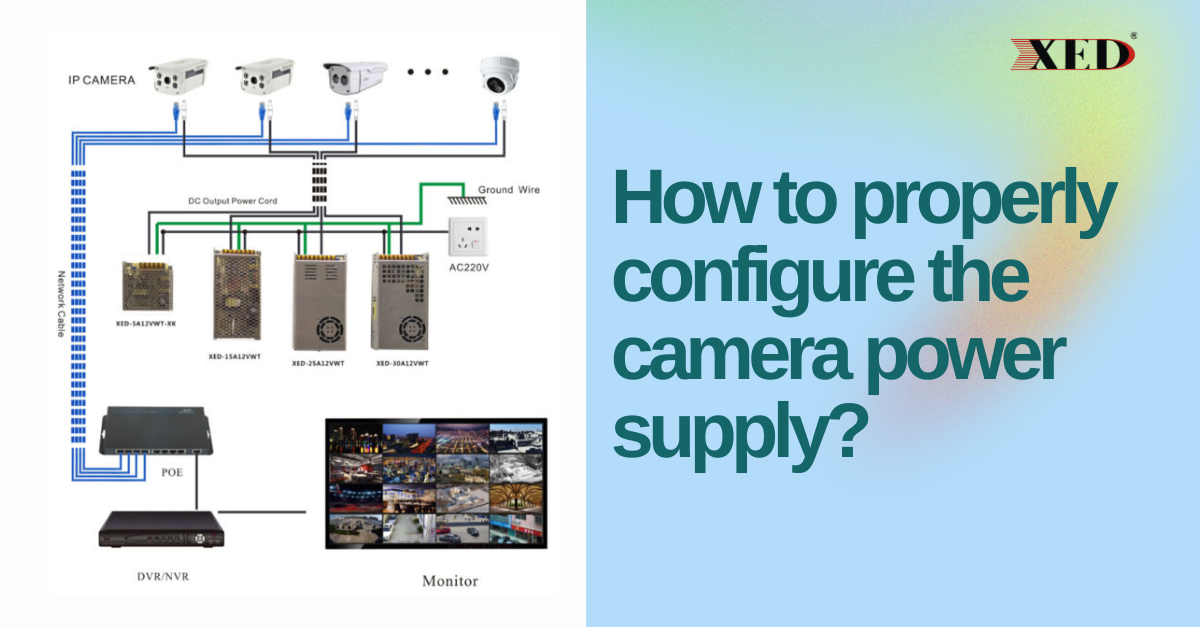
In actual projects, common power supply methods include 220V AC centralized power supply and 12V DC independent power supply. The former is suitable for high-density, relatively close-proximity camera installations, offering advantages such as easy management and low cost. The latter is more suitable for distributed, long-distance deployments, offering excellent fault isolation and minimal impact from single-point failures. For high-end projects, PoE (Power over Ethernet) can also be considered, enabling integrated data and power transmission.
5. Analysis of practical application cases
Suppose a commercial building project requires the installation of 100 fixed box cameras, each with a rated power of 4W.
• Total camera power rating: 4W × 100 = 400W
• After accounting for transient current: 400W × 1.3 = 520W
• Taking into account line losses: 520W × 1.3 = 676W
• Allowing for expansion: 676W × 1.3 ≈ 878W
Therefore, it is recommended to select a power supply with a total power of at least 880W and to properly distribute the load across the different power supply circuits.
6. The key role of wire and voltage adjustment
When supplying power over long distances, in addition to increasing the power supply wattage, cable material and diameter must also be considered. A thicker copper power cable significantly reduces impedance losses. For ultra-long-distance transmission, appropriately increasing the output voltage (for example, using a 24VAC power supply) and then reducing it at the camera end is also an effective engineering practice.
7. Power supply configuration recommendations for special environments
Power supply and camera performance may vary in low or high temperature environments. In cold regions, attention should be paid to the low-temperature startup capabilities of power supply equipment. In hot locations, thermal design and temperature derating should be emphasized. Furthermore, surge protection devices should be installed in areas prone to lightning strikes to prevent damage to equipment caused by power grid fluctuations.
8. Future system expansion and intelligent management
Good power planning requires a certain level of foresight. In addition to power redundancy, it also includes the use of intelligent power systems that support remote monitoring and management. These devices can monitor each circuit's current, voltage, and operating status in real time, identifying anomalies and issuing alerts promptly, greatly improving system maintainability.
Comprehensive planning and scientific implementation
Configuring camera power is a systematic task that integrates electrical engineering knowledge and practical application experience. It requires not only a precise understanding of device characteristics, transmission environment, and dynamic loads, but also an optimal balance between cost-effectiveness and reliability. Through scientific calculations, rational selection, and rigorous construction, an efficient, stable, and easily scalable surveillance system power architecture can be established, providing a solid foundation for the long-term operation of security systems.
What's the difference between nominal voltage and rated voltage of power adapter?
Visual Inspection Guide: How to Detect Switching Power Supply Defects Early